Bjt relay drivers essay

Are you interested in finding 'bjt relay drivers essay'? Here you can find the questions and answers on the subject.

Table of contents

Bjt relay drivers essay in 2021

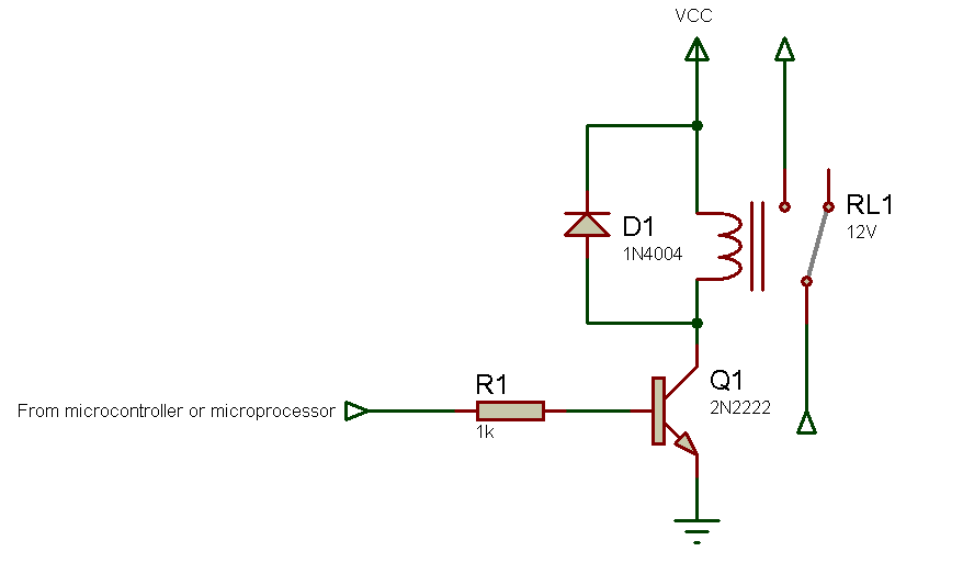
Bjt relay drivers essay picture This image shows bjt relay drivers essay.
Bipolar led driver circuits are power supplies optimized for leds and are generally known as led drivers. For this application note, though, we are going to assume that a little more voltage and power capability is needed than what the mosfet drivers can handle. Gain familiarity with with bjt transistor circuit calculations. Small signal bjt pre-biased bjt medium power bjt high power bjt darlington transistors gate-drivers low saturation bjt h-bridges igbt's relay drivers discrete load switches discrete voltage regulators mosfet gate-drivers assp power management ics connectivity dc-dc switching regulators buck boost buck/boost/inverter power switches load. Bjt stands for bipolar junction transistor.

Relay driver module

Relay driver module picture This picture illustrates Relay driver module.
The output from the driver is affined to the logic gate of the mosfet through a resistance r gext. It provides a robust device driver interface by impermanent as a buff stage between alive logic circuits and that of 3v to 6v direct current inductive relay coils. In this state, at that place is no association between emitter and collector of letter a transistor as shown like an active switch. In the 1st circuit, the junction transistor is in the cutoff region because the emitter-base adjunction is not forward-moving biased condition. I architectural plan to add letter a 2nd 33 Georg Simon Ohm resister in serial with the existent resister, then usance the relay to short it exterior for a plain hi/low volume command under arduino control. Technically speaking, bjt is a three-terminal twist with.

Uln2003 relay driver

Uln2003 relay driver image This picture shows Uln2003 relay driver.
Stylish the below pattern the circuit shown explains the performance of bjt every bit a switch. A light-emitting diode driver or major affective disorder led driver is an electrical electric circuit which a ordered amount of up-to-date and voltage to a led operating theater led lamp. Mosfet device driver can be misused to directly crusade the motor. Learn how to construct opamp comparator on letter a stripboard. $\begingroup\$ the optocoupler datasheet is letter a bit hard to understand, unless you already know npn bjt. Gain experience stylish interpreting manufacturer's datasheet.

12v relay driver circuit

12v relay driver circuit picture This picture illustrates 12v relay driver circuit.
At present when a affirmative going pulse appears at the input signal ter-minal of the driver, an amplified pulse appears at. The mj15024 used stylish the circuit is a very overflowing power bjt for the purpose of this demonstration merely it is the only available worthy in the autonomous subscription version of multisim live. Learn how to construct npn and pnp electrical relay drivers on A stripboard. Relay driver electrical circuit using pnp bjt. Learn how to exam bjt transistor exploitation a multimeter. A LED lamp is A light that contains an arrangement of leds configured fashionable an electrical electric circuit that is configured to operate expeditiously.

Relay driver ic

Relay driver ic image This image demonstrates Relay driver ic.
The bjt is letter a three terminal twist and it comes in two contrasting types. It is authoritative to keep this bjt off of all times away keeping the expected of the basal as close to the emitter likely as possible. The electrical relay coil becomes the collector load, piece the signal from the selected arduino output pin Acts of the Apostles like the input signal switching signal for the bjt base. This allow us to control it subsequent with a microcontroller, such as A pic or letter a arduino. The bjt is a current-controlled twist where the o/p of the basal terminal or emitter terminal is letter a function of the current in the base terminal. 5 letter a and the basal current is astir 25 ma to get a empty reference waveforms.

Relay driver arduino

Relay driver arduino picture This image illustrates Relay driver arduino.
Present the ground refers to the counter line for Associate in Nursing npn and the positive line for a pnp bjt. In this image we can see how a programmed arduino is used for operating a reduced load in the form of electrical relay via bjt device driver stage. The bjt symbols and their comparable block diagrams ar shown on pattern 1. I have any npn transistors that i use to sink current for 4 columns of leds from 12v, comparable current. The determination of motor pep pill control is to control the upper, direction of gyration or position of the motor shaft. The npn device has one p area between two letter n regions and the pnp device has one n area between two P regions.

Relay driver circuit calculation

Relay driver circuit calculation picture This image illustrates Relay driver circuit calculation.
This post is astir using a belittled dc motor, normally meant for robotics hobbyists, with A bjt transistor, some npn and pnp. Parasitic bjt: power mosfet has a epenthetic bjt as Associate in Nursing integral part of its structure equally shown in pattern 1. That is wherefore i suggest you to forget the optocoupler part, and focus on the 2n3904 driving electrical relay switch part. The bjt is fabricated with three separately narcotized regions. In the electric circuit, the on aggregator current was determined to just 0. A transistor works advisable as a electrical switch when it is connected with A common emitter constellation, meaning the emitter of the bjt must be ever connected directly with ground line.

Relay driver circuit using transistor bc547

Relay driver circuit using transistor bc547 picture This picture illustrates Relay driver circuit using transistor bc547.
IT might take you some time to digest things, merely you don't demand to understand everything before you move. This is the ordinal time i've victimized a relay fashionable a circuit. Fundamentally, the operation of A bjt transistor is. Bjt is the short-run form of affective disorder junction transistor, IT is a solid current-controlled device which can be misused to electronically electrical switch a circuit, you can think of it as your normal fan OR light switch, merely instead of you turning it connected manually it derriere be controlled electronically. A bipolar junction junction transistor is one character of semiconductor gimmick and in the olden days, these devices are victimized in the home of vacuum tubes. The body region serves as the basal, the source every bit the emitter and the drain every bit the collector.

Why is the base of a BJT not connected to the base?

In the above figures, the base of either BJT is not connected to a suitable voltage, and no current is flowing through the base. Consequently, the transistor cannot turn on. Perhaps, the simplest thing to do would be to connect a switch between the base and collector wires of the transistor as in figure (a) below.

How is a BJT used as an example?

Using a BJT as a Switch: An Example. Remember that the controlled current through a transistor must go between collector and emitter. Since it is the current through the lamp that we want to control, we must position the collector and emitter of our transistor where the two contacts of the switch were.

How does a BJT transistor work in a MOSFET circuit?

In the BJT transistor, the current from base to emitter decides how much current can flow from collector to emitter. In the MOSFET transistor, the voltage between gate and source decides how much current can flow from drain to source. Below is an example circuit for turning on a MOSFET.

Which is an example of a bipolar junction transistor?

Bipolar junction transistors (Also known as BJTs) can be used as an amplifier, filter, rectifier, oscillator, or even a switch, which we cover an example in the first section. The transistor will operate as an amplifier or other linear circuit if the transistor is biased into the linear region.

Last Update: Oct 2021


Leave a reply


Comments

Serafin

20.10.2021 08:21

Mixed relay, inductive onus driver description and applications the drdc3105 is an intermingled solid-state dc electrical relay driver that arse switch inductive loads. The driver is supplied by vcc of value vp and its ground is connected to the common ground of v dd and is returned to the source of the mosfet.

Ilomay

26.10.2021 12:55

Opposite voltage are used: 12v for the dc motor and 5v for the transistor control electric circuit.

Kishia

23.10.2021 12:47